Friday, July 29, 2011

Large Horizontally Oriented Water Heating Collector with a Unique Heat Storage System

This is a very nice solar water heating system done by Bob and Dave.  
The 24 ft wide collector fits nicely under the deck.
Aside from being very well built and aesthetically pleasing, it has some unique design features:

  • Instead of running the collector manifolds horizontally along the top and bottom and connecting the manifolds with many vertical risers with fins, this collector runs the manifolds vertically on the left and right ends.  The vertical manifolds are then connected a small number of 24 ft wide "hizers".  This saves a lot of fittings, a lot of soldering, and a lot of labor.  This is one of the nice things about building a system yourself -- you can adapt the design to your specific situation.
  • The heat storage for the system takes the form of a an insulated vault containing several plastic barrels that store the heated water.  Since the barrels were free, this makes for pretty inexpensive storage.  The heat exchangers are pipe coils that are wound inside of smaller drums that fit inside the larger barrels.   

Picture shows the 24 ft "hizers" being laid out.
The heat storage vault with the 4 barrels that store heated water.
The heat exchanger pipe coils wound inside of smaller drums.
So far, the system is being used primarily for domestic water heating, but the collector design and heat storage scheme certainly make it a good candidate for solar space heating as well.

Several pages of design, construction, and cost details on the system here...

More solar water heating systems...
More solar space heating systems...

Thanks very much to Bob and Dave for taking the time to document the system!

Gary


Wednesday, July 20, 2011

Converting a Clothes Dryer to Use Solar Heated Attic Air

Randy has done a really interesting new project that reduces the energy used to dry clothes at his house by a factor of five!

His scheme converts a regular dryer to use hot air supplied by his unique attic solar heating collector instead of heating the air within the dryer.  A duct from his attic collector supplies air to the revamped intake of the converted dryer.  The dryer exhaust air is vented out through the wall in the normal way.

The converted dryer on the left and the new intake ducting on the right.
The upper duct connects to the attic solar collector.
Dryers are major users of energy in homes. A Canada study shows that dryers typically use 930 KWH a year to do 416 dryer loads (2.23 KWH per load). Nearly all of this heat energy is simply expelled outdoors (wasted). In addition, as the dryer vents air outside, it pulls fresh air into the house which has to be heated or cooled (depending on season) to room temperature -- this can easily add another 300 KWH plus per year.    Since refrigerators have become much more efficient over the years, dryers now stand out as the applicance using the most energy in many homes.  It is amazing to me that Energy Star has taken no action in this area -- but, I guess that's another story.

For all the details on Randy's dryer project...

I've also added a new section that gathers together several ideas and projects that save energy on clothes drying ...

Some highlights on Randy's dryer conversion:

The silver duct on the right is the dryer air inlet.
It takes air from the dryer cabinet on the lower right, and supplies it to the drum.  The idea is to change this so that
the air source is the attic solar collector.
Randy pluged the normal air inlet (lower right), and
added the 4 inch connection for the new attic air source.

The upper duct is the new air inlet ready to be hooked up to the attic air source.
Lower duct is the normal dryer exhaust vent that goes to the wall.


The duct that brings the hot air from the attic collector
down to the dryer inlet.


The temperature on the right is the attic collector temperature.
Temperature on the left is the dryer inlet temperature.


Drying a full load of mixed clothes takes 90 minutes, and uses only 0.6 KWH.


Gary July 20, 2011

Tuesday, July 19, 2011

A DIY Solar Water and Space Heating Project

Eric describes his new solar water heating system that will be used for both domestic water heating and radiant floor heating.

The first collector for Eric's system.


The design is based on the $1K Solar Water Heater, with some refinements and improvements for Eric's situation.  The system is extended to do both domestic water heating and some space heating.

All the details are posted on Eric's blog -- Radiantenergy.org...

Here are a couple highlights:


Very nice job on the absorber plate.


The base for the tank on conrete pavers.


The pump that cirulates tank water to the collector.

Thanks very much to Eric for sharing the details.

For more examples of $1K systems and other solar space and water heating systems...

Gary

Thursday, July 7, 2011

Our New 2500 Gallon Rain Water Collection System

We just finished up a rain water collection system a couple weeks ago and now have the full construction details up on the site.
The system uses the roof of my shop and carport (925 sf total) to collect rainwater into a 2500 gallon polyethylene container.  We then use  a small pump to pull water out of the container for watering the garden and trees.
The new water collection system.


Building the system included adding gutters to the roof, running 3 inch PVC collection plumbing from the gutters to the tank, doing a first flow diverter, adding an overflow pipe, and working out a simple pump arrangment to get the water over to the garden.

Getting the tank off the truck


The writeup goes through the details on how we picked the tank size using the very handy CLIM20 weather summary  (free from the gov).  And then goes on to show all the details on placing the tank and putting in all the plumbing.  All in all a pretty easy job.

Gutter to tank plumbing.


All the details on the rain collection system here...

More on rain water harvesting, grey water, toilets, ...

It looks like the system will provide about 7000 gallons a year depending on how our actual usage pattern works out.  We are planning to use the water only for garden and tree watering.  Of curse, it also provides some water for emergencies.  We may do a larger system using the house roof later depending on how this works out.

So, this system coupled with the switch over to all dual flush toilets is saving a lot of water use at our place.   This is gettting to be more and more important in our valley.  The one troubling aspect of all this is that we still use a lot of water to water the lawn through the summer.  I don't even want to do the estimate on how much because I'm sure I won't like the number.  I guess that the answer to this is to go to a more native plant, low water landscaping scheme -- anyone know any good resources for planning this kind of landscaping in the Rockies?

By the way, I've added a new comment system for articles on Build It Solar, so it will be possible to easily comment on, ask questions, and discuss each article -- I encourage everyone to use this.
The first article with the new comment system is Randy's attic, and the writeup on the new rain water harvest system is the 2nd.

Gary

Monday, July 4, 2011

Randy's Invisible Solar Attic Space Heating Collector

Here is another simple scheme for using solar heat from the attic to provide free space heating.
The lower plenum and collector channels formed by
the roof trusses.
Randy sheeted across the back of some of his attic roof truss bays to from the channels for a collector.  He then added an intake plenum at the bottom and a exhaust plenum at the top.  So, air flows from his living room via a 12 inch duct to the intake plenum, then up through the truss bays picking up heat from the under surface of the roof, and then into the exhaust plenum, and finally back to the living room via another 12 inch duct.  The flow is powered by an attic vent fan that includes a 93F thermometer to turn the system on when the attic air gets up to a useful temperature.

While the system is currently prototyped in cardboard to see how well it worked, Randy plans to replace the cardboard with rigid polyiso foam board.

One remaining challange is a good backdraft damper to prevent cold air from thermosyhphoning into the living room at night -- any ideas?

All the details on Randy's solar attic heat project...

Randy is planning to try picking up attic air to run the clothes dryer with.

The collector is invisible from the outside.

For more information on using solar attic heat ...

Note that I'm trying a new comment system that you will see when you go to Randy's project page -- I'd appreciate hearing any feedback on the system or problems using the system.

Gary

Saturday, June 11, 2011

Solar Heat from the Attic

I think everyone has gone up to the attic and been surprised by how hot it is.  Its just a small step from observing the heat to wondering if you could make use of it somehow. 

I added a new section that gathers together a few schemes for using attic heat for space or water heating, and other things -- here are a few samples -- see the link below for all the details.

Tim just did a project on EcoRenovators that makes use of attic heat in a nice simple way --he  just blows hot attic air down into the house when the attic is hot and house needs heat -- nice and simple, and it works.

Tims heat from the attic system
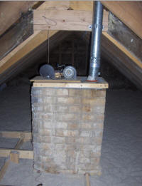
This is Tim's setup -- it uses a chimney that is not in use anymore to channel the air down to the kitchen.  A homemade differential controller decides when to turn the blowers on.


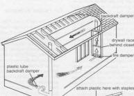
The picture to the left is the "Black Roof" solar heating scheme.  This scheme basically harvests attic heat for space heating with just a few simple components and a blower.  It is said to be effective in cold climates that get quite a bit of sun -- eg Colorado.


There have been a number of schemes to use the attic heat to preheat domestic water.  This is a recently announced commercial offering that uses PEX tubes installed in the attic vent system to harvest heat.


Another idea that I like is picking up the inlet air for the clothes dryer from the attic.  Electric clothes dryers are big time energy users -- they not only use about 4 KWH of electricity per load, but they also end up sucking cold outside air into the house as they blow the air they have just heated out into the cold (wasting all the heat they just added to it).  If you could work out a way to pull hot air from the attic for the dryer it would eliminate all this cold air infiltration and the drywer could use less electricity since its inlet air would be hot already.  The nice thing about this is that you can time the drying to coincide with times when the attic is hot.

The ability to pull useful heat out of the attic will depend a lot on the climate you live in.   In our very cold climate, the space heating applications would be limited to the shoulder seasons, but this still could be an important source of heat.  The link below has my logged hourly attic temperatures for about a year.

If the use of attic heat idea could be incorporated in the initial design of the house there are all sorts of interesting and cost effective things that could be done to make the attic an effective heater.  Things like designing the attic to be a more efficient collector through the design of the roof surface, the attic vent system, and selective use of insulation on non-collecting surfaces could make the attic a fairly efficient and very large solar collector for not a lot of extra expenditure.  Introducing glazing could make the attic collector competitive with commercial air heating collectors.   

Got any ideas on any of this?  Have you used attic heat?  How?


All the details on the schemes above as well as several more interesting ideas are detailed here...

Gary

Tuesday, June 7, 2011

Efficient Cars Roundup from Solar Today

The current issue of Solar Today has their 4 th annual Efficient Cars Roundup.  I did not see the first three, but the fourth is a dandy -- partly because there is quite an interesting batch of new efficient cars to look at, and partly because of the excellent data table that is included in the article.
The interesting batch of new cars includes several real, honest electric cars (like the Leaf), several real, honest plug in hybrids (like the Volt), and a good selection of regular hybrids, gas engines, diesels, and one Honda CNG powered car.  Its nice that we have gotten to the point where hybrids can be referred to as "regular".


If you are one of the people (like me) who really wonder whether an electric car with its zero tail pipe emissions is really so squeaky clean when you trace the electricity back to the electric power plant (which has a 50 - 50 chance of being coal fired), then this is a good article to read.  The table that comes with the article has columns like: "12K mile E-mode carbon footprint with 100% coal", and "12K mile E-mode carbon footprint with 50% coal".   It also includes emissions data for using biofuels, 10 yr cost for both electric and fossil fuels, and more.   This is the best summary I've seen as far as being able to make quick comparisons on operating costs and green house gas emissions.  Much more helpful than the new EPA new car window stickers.

I think that some of the comparisons will surprise you.

The article is a free download from Solar Today, and there is even a downloadable spreadsheet version of the table.

Good stuff.

For more on efficient transport options, see my "Solar & Efficient Vehicles" page...

Gary

Wednesday, May 25, 2011

Mother Earth News Article on Our PV System

Sorry, I have to crow a little -- our DIY grid-tied PV system is the "Top Story" in the new issue of Mother Earth News, and is on the cover!

This is the June-July 2011 Mother Earth News and is out on the our local newstands now (May 25). 

This is the system I put in my back yard last year.  Its a grid-tied system and uses the Enphase micro-inverter grid-tie scheme.  In this arrangement, each PV module gets its own small (190 watt) grid-tie inverter.  These micro-inverters are daisy chained together, and the combined output is carried back to the house as 240 VAC house power.  After going through a disconnect switch, the power just hooks up to any free circuit breaker in your regular breaker box.

One of the interesting features of the Enphase system is that it sends data back over the intrnet to the Enphase mother ship, and they provide a webpage for your site that can be monitored via an internet browser.  This is the page for my PV array...


I did all the work on the system myself, and found the whole process pretty straightforward  -- even the permitting and utility company people were friendly and helpful. 

The article has quite a bit of detail on the system, but if you want more detail, there are many pages of information on the design, permiting, building and performance of the system here...

The article is now online at the Mother Earth News Site...

My system is a grid-tied system, so if the grid goes down, so does my PV.  If you are interested in off-grid gird-tied with battery backup, there is lots of info those systems here...


Gary

Saturday, May 21, 2011

Solar Air Heating Collector Testing -- Which DIY Solar Collectors Perform the Best?

DIY solar air heating collectors for space heating can offer the best bang for the buck of any solar project I know.  These collectors are simple and cheap to build and can have payback periods as short as one season!  They offer a particularly attractive option to the Do-It-Yourselfer -- commercial solar air heating collectors with prices pushing $2000 can literally be built as DIY projects for $200!

Side by side testing of two solar air heating collector designs

One of the biggest questions facing someone wanting to build one of these collectors is to decide which of the many collector designs out there to build.  Its fairly easy to look at the designs and evaluate construction difficulty and cost, but the big missing factor is the efficiency of each design. 
 
Scott and I have been doing a winter long set of testing on some of the common DIY solar air heating collector designs to try and get a handle on comparative performance.   We have adopted the approach of building full size prototypes of each collector design.  These prototypes are identical except for the absorber and inlet and outlet details that make a design unique.  We then test two of the collectors side by side such they both see the same sun, ambient temperature, wind, etc.   In these tests, one of the two collectors is always the standard baseline design, so each new collector is being compared to the same baseline design.   This procedure makes it much easier to get a true comparison of the various designs. 

Performance plot for side by side collector performance test

Scott has a very nice video that does a good job of explaining the Physics of solar collectors and some of the testing procedures...

Blower and airflow measuring setup for collector testing.

I've pasted in the summary of results for the winter of 2010 - 2011 just below.  If you want a detailed description of each collector design and the testing that was done on it, see the full report...

As it turns out, one of the simplest collector designs did very well, so you can have simplicity  and high performance with the same design.

-------------------------------------------------------

Summary of Tentative Results for  Winter of 2010 - 2011 Tests:

This is a tentative ranking of the collectors from best overall down based on the testing that was done.   

I ranked this the best because it has a great combination of high performance, low cost, and is a very easy build.
This collector also has a low pressure drop which means a smaller (maybe quieter and cheaper) fan can be used to drive it.
The screen collector surprised both Scott and I -- we initially included it because it is easy to build, and the thinking was that even it is not up to the performance of some of the others it might be a winner in low cost and easy build.  
As it turns out, none of the other collectors did better in performance.
Performance rating: base  -- this was the best performer and is the base for performance drops shown below for the other collectors.

In the performance area, this collector was basically tied with the screen collector, and there may be further optimizations that could be done to improve its performance from what was tested.
Its a relatively simple build, but harder and more expensive than the screen collector.
The pressure drop through this collector is low (which is good).
Performance rating: About equal to the base screen collector

While this collector did not perform as well as the screen collector, I would hold off on judging performance until a more optimized one can be tested.
On the negative side, its the most expensive of the collectors listed here to build, and its not clear (to me) exactly what needs to be done to the design to get a more even flow distribution.
The pressure drop through the collector is low (which is good).
The downspout collector appears to be well suited to long narrow collectors that might be difficult to do with a screen or soffit collector?
Performance rating:  In my test, 40 to 50% off the screen collector, but my downspout collector was not optimized, and can improve.

This is the old standby design that has been popular for many years.
The version that we tested turned out to have performance that was not as good as the screen collector.
The backpass collector had the highest pressure drop of any of the tested collectors (which is bad).
There are a lot of variations possible on this design, and its certainly possible that other versions would do better.
Performance rating:  About 10 to 20% off the screen collector.  Optimization of the baffles would improve the backpass collector.

This one certainly is the winner on ease of build and cost -- its literally an empty black box with air blown through it.
The performance was poor.
Testing it sort of answers the question I get a lot saying "Why not just build and empty black box and blow air through it? "
The answer is that you can do this, and it works, but you are giving up a lot of performance compared to other designs.
It may be possible to start with an empty box design, and figure out a way to add good baffling that would get a more even distribution of air over the full absorber, and make this design much more competitive.  On the other hand, you could start with an empty box and add a couple layers of screen :)
Performance rating: About 50%  to 60% off the screen collector -- that is, adding two layers of window screen roughly doubles the heat output!
These results agree with Scott's tests with the exception of the downspout collector, which Scott did not have a chance to do a side by side test on.  I think that it is significant that we were able repeat each others results with completely independent test setups.
Things to bear in mind in interpreting the performance results:
  1. None of these collector designs has been optimized for best performance.  They can all likely benefit from design refinements -- some likely more than others. 
  2. Coming up with a good method to measure airflow accurately in order to insure that the two collectors being tested side by side were getting the same airflow proved to be very difficult.   The methods used included: time to inflate a large bag of known size, velocity measurements with a Kestrel turbine style anemometer, using the flow generated voltage of PC fans in the collector flow, a hot wire anemometer, and pitot tubes to measure.  The methods changed from test to test, and the fact that some of these methods have an unknown amount of error introduces some uncertainty into the results.
  3. The original plan was to identify one collector design as the baseline, and to include this collector as one of the two collectors in each side by side test -- this way each new design was always being compared to the same baseline design.  The original choice for the base collector was the backpass collector.  But, after testing the screen collector and seeing how well it did with such a simple and easy to build design, we decided to change the baseline to the screen collector -- this makes it easier for anyone who wants go join in this testing to do so.  But, this again introduced a bit of uncertainty in the test program.
  4. The weather was different for each test, so basically each pair of collectors was tested on a somewhat different part of its efficiency curve.  This was one of the main reasons for always including the baseline collector in each test.   I did attempt to do each test on a clear day with outside temperatures that are typical of real winter conditions (the downspout collector test was the one exception with a fairly high 49F ambient temperature).
One final note on the testing is that as a sort of check on the whole process, I built a 2nd screen collector that is the same as the first one.  I tested the two screen collectors against each other in a side by side test.  I used the same setup, blowers, flow measurement techniques as are described above for all the other tests.  So, this is a check on the whole side by side method of testing and on the instrumentation.  The difference in heat output between the two was 3%.  Of course, if both collectors were completely identical and the instrumentation, flow rate setup, ... were exactly the same for both the heat output difference would have been 0%.  I guess that one message here is don't be looking at differences of 2 or 3% as significant -- these kinds of differences arise from small differences and construction and measuring techniques.

I'm probably going to do more testing next winter with an eye toward repeating some of these tests with a better airflow measuring setup, and then (hopefully) get into some changes to improve the design on some of them. 
I'd very much like to hear from anyone who has ideas on what was done this last winter and what might be done next winter.  Any feedback on whether any of this was helpful in deciding what kind of air collector to build and/or deciding to build one at all.  Gary...

Gary

Thursday, May 12, 2011

Kevin's Grid-Tied, DIY, Micro-Inverter PV System

In a five part blog Kevin goes through the whole process of planning, permitting, getting approvals, and installing a 3.84 KW grid-tie PV system.

3.84 KW grid-tie PV array on roof
After working out what size system made sense, and investigating the local permitting, approval process and net metering arrangement,  Kevin selected a kit that included the PV modules, micro inverters, roof mounting racks, and many of the rest of the parts needed to do the system..

Kevin's system is a roof mount, and he provides some good pictures and description on doing the roof mount and installing the modules and micro-inverters on the mount rails.
Roof mounting rack with micro-inverters installed.

Getting the large, awkward, and expensive PV modules up on the roof deserves some thought -- Kevin came up with a very nice track and sled arrangement to get the modules up on the roof.
Sled to get PV modules on roof.


The rest of the installation covers plugging in the PV modules, adding the AC disconnect and placards, and getting the new net meter installed.

Kevin signed up for the Enphase realtime online tracking for the system, so he (or you) can see how its doing at any given time online right here...


For all the details and pictures on Kevin's system go here to Kevin's blog...

For details on other PV system installation (on and off grid) go here...

With the addition of Kevin's system to the my system and Guy's system, there are now three very detailed descriptions of installing grid-tied, micro-inverter systems at the link just above.
There will also be an article on my system in the next issue of Mother Earth News.

Gary
 
/* Start Analytics ---------------- */ /* End Analytics ---------------- */